Repair stencils and Reballing stencils in a lasercuting and laserwelding production process

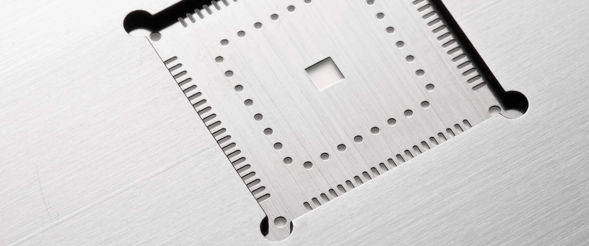
Repair stencils and Reballing stencils in a laser cutting and laser welding production process

Since more than 10 years LaserJob is manufacturing repair stencils in a lasercut and laserwelding process. With the introduction of the SMD – Technology the constantly variety of component forms and component leads constantly increases, especially of the area array components, of the rework systems and of the repair stencils. The ever smaller becoming pitch - distance from component leads - represents a further challenge at the repair systems and repair stencils. In air controlled production rooms LaserJob is manufacturing repair stencils for all repair systems and repair stations. In strained conditions apertures and pad areas are cut in a stainless steel foil and a frame is welded on in the correct position. With this procedure we ensure that the sensitive stencil foil is protected against external damage and is present in strained conditions.

Benefits

Positioning help for all components

Adjustable geometry on the printed circuit board

Absolute planar

Stability with welded frame 


Repair - stencil

Repair - stencil

in laser cut and laser weldíng technology

Reballing - stencil

Reballing - stencil

Re-balling of BGA´s or CSP´s with a re-soldering process.

Repair - stencil

Repair - stencil

for a special type of component

Repair - stencil

Repair - stencil

with a special holder for repair systems

What are the standard sizes of a repair stencil?

As a standard feature, the repair stencils are offered in sizes from 10 mm x 10 mm to 100 x 100mm. 

Other sizes and geometries are available on request. 


How can QFN / MLF components be reworked?

Advanced Packages, such as QFNs or MFLs, have their connections on exterior sides beyond the chip, and have direct contacts, via side bumps. The QFN-connectors are printed using a mini stencil, solder paste and squeegee in a fast and accurate process, thus minimizing component stress. The printed component, before being soldered to the substrate, is analyzed by optical inspection. The mini stencil is removed after the reflow process to ensure higher process stability and to avoid solder paste sloughing and smearing.


How is the exact positioning of the component guaranteed?

The printing mask is welded together with the carrier plate or carrier frame. The cut-out section, or nest, is a helping tool for accurate positioning of the component. Misaligned components are therefore prevented. 


Which documents and information do we need from you?

For complete processing, we need the drawing of the component with tolerances. 


You may also be interested in

Schreiben Sie uns
[Translate to English:] Sie erreichen uns jederzeit unter der Telefonnummer: +49 (0)814152 77822
Call us

Write us at:

LaserJob GmbH
Liebigstraße 14
82256 Fürstenfeldbruck
Deutschland